PROJECT EMBERWING / DESIGN DOSSIER / 15 OCTOBER 2026
Waterborne utility.
Vertical flexibility.
An original autonomous amphibious firefighting aircraft. Exploratory industrial design, not an airworthy design, certified capability, or validated simulation.
Revision W · Fuller body, cleaner wing and tail
The current aircraft has a rounded, wider forebody and a restrained taper into a simpler V-tail. Straight wing and tail edges replace the previous changes in sweep. A single centered dorsal inlet and aft exhaust form one visual installation, with separate cold-air and hot-gas paths still requiring engineering. The supplied Thunder model informed exterior proportions only; no reference mesh, texture or branding is incorporated.
| Current geometry | Revision W |
|---|---|
| Hull length / maximum beam | 14.374 m / 2.278 m |
| Wing span / gross reference area | 18.4 m / 66.06 m² |
| Rotor diameter / axis spacing | 7.2 m / 19.2 m |
| V-tail projected span | 7.4 m |
| Water target | 3,000 L · two 1,500 L tanks |
The floats move 100 mm outward on each side to retain the stowed-wheel clearance with the wider hull. A wider waterplane is not proof of stability: trim, metacentric height, slosh, planing and wave behavior remain unverified.
At the loaded mass, a clean CLmax assumption of 1.5 and a 30° bank produce 1.3× stall-speed screening values of 59.0 m/s at sea level and 67.0 m/s at reduced density. The animated scoop speed is illustrative, not a demonstrated wingborne capability. The level-water displacement estimate gives a loaded datum near −0.206 m; the drawing datum remains −0.240 m. Rigid geometry and mechanism tests do not establish structural strength, thermal performance or stability.
Integrated front sensor suite
The original nose carries separate flush apertures: a 500 × 300 mm lidar panel below two independent daylight/thermal cameras, and a smaller opaque forward-radar cover beneath it. A muted bronze lidar coating distinguishes it from the dark camera windows. Small side cameras, a downward optical-flow window, two radar-altimeter antenna panels, the GNSS radome, air-data probes and avionics complete the exterior concept.
This is original concept geometry, not selected hardware. A larger lidar window does not establish performance. The new radar and optical-flow details are placeholders; actual installed mass, power, fields of view, spectral windows, cleaning, de-icing, sealing and spray exposure remain unresolved.
Earlier revision record
The following sections preserve the original design history and its assumptions. Earlier dimensions, mass/power figures, VTOL water allowances and clearance results are superseded by revision W above. The A–E engineering workbench also retains its historical reference geometry.
Revision Q · Shallow scoop travel and connected filling ducts
The previous 105° fold is replaced by a 360 mm guided vertical lift. The mouths retain their forward-facing orientation and park just behind the step instead of disappearing deep into the hull. The deployed mouths are 60 mm lower. Matching openings through the hull and overlapping inboard float skins remove a hidden clipping surface.
Each curved scoop now has a hollow sliding neck, an overlapping fixed receiver, a seal housing, a continuous wet-side fill riser and a bolted inlet through an actual tank opening. Two guide bushings and a hydraulic cylinder carry each probe. Cutaway shows the complete path; the two 1,500 L tanks retain their capacity.
The planing step is retained, with a coated face matching the hull. Stepped seaplane hulls release their afterbody from the water as they plane; see the FAA Seaplane Operations Handbook. An aft-of-step intake need only expose its working portion below the preceding surface. Static rays check that this model has an exposed lower intake area; they do not predict flow separation or spray.
Evidence and assumptions: the Bombardier Museum’s CL-415 artifacts inform the visible vaned quarter-bend. Field Aviation patent US4474350A discusses both earlier pipe-connected probes and its own separate-receiver arrangement. It is not proof of Canadair’s internal installation. The present vertical lift, sliding duct, seals, dimensions and mounting are original Emberwing design assumptions.
Checks cover the actual moving meshes at 81 positions per probe in both detail levels, the neighboring hull/float skins, fixed receivers, fill ducts, open tank ports, hydraulic endpoints and the shared mission spray datum. The exported mechanism is compared against the source after loading. Pressure and structural loads, seal life, grit tolerance, flooded-well buoyancy, drainage, fail-safe retraction and the step wake remain unresolved. The 3,000 L / 15 s fill schedule is illustrative, not measured capture performance.
Revision P · Coordinated response flight
The mission can fly one, three or four aircraft. Every member independently departs, converts, scoops 3,000 L, transits, drops, returns and lands at its own pad. Total flight capacity is 9,000 or 12,000 L; the full flight ends after the last shutdown at 7:27 or 7:33. The camera can frame the entire flight or follow any call sign. Water levels, surface controls, wakes, discharge and terrain wetting follow each member’s own mission clock.
The original choreography uses six-second station intervals, loose lateral transit offsets of −60 / +60 / −120 m and height steps of +8 / +16 / +24 m. Aircraft settle into separate −24 / +24 / −48 m work lanes for collection and delivery, and use pads on a 64 m grid for sequential departures and landings. Full water loads remain wingborne. These numbers are design assumptions, not certified separation or firefighting procedures. The smaller standalone drop study extends its approach over the surrounding hills at working clearance.
The DOI / USFS Firefighting Flight Operations lesson, 2021 describes coordinated flights of scoopers and the need for sufficient spacing and supervision. It does not prescribe this concept’s intervals. Wake and rotor interaction, closed-loop formation control, airspace coordination, operational sequencing, collision avoidance and failure handling require future engineering and operational work. These are authored mission illustrations.
Numeric verification samples all mission paths, each aircraft’s water budget, rotor envelope, probe immersion, controls and parking positions. The complete four-aircraft sortie has at least 63.69 m center separation and 1.75 m sampled rigid-rotor clearance above the terrain/lake. These visual checks exclude flexible blades, waves, wind, wake interaction and uncertain aircraft performance. Full rendering uses detailed shadows around the selected member and approximate silhouette projections for companions; one shared lake serves the whole flight.
Revision O · Coordinated flight surfaces
All eight control surfaces now respond to the mission maneuvers. Differential ailerons initiate and arrest roll, returning near neutral in a sustained bank. The V-tail mixes pitch and yaw commands. Its pitch trim changes with flap setting, turn load and balanced water payload. Primary aerodynamic controls fade toward neutral in hover.
Flaps deploy before departure, change during conversion and approach, hold through the scoop run, retract during transit, use a reduced setting for delivery, and deploy for landing before stowing after touchdown. The ailerons remain independent. Cached, finite-rate actuator tracks preserve the same position during playback, pause, replay and reverse scrubbing.
The wing hinge axes now follow the camber centres, the control leading edges are relieved, and the fixed actuator housings end ahead of the moving panels. Rigid checks cover both model detail levels and full control travel. A seventh portable animation demonstrates pitch, yaw, roll and flap operation.
Concept assumptions: flap limit 25°; aileron 18° up / 11.7° down; combined ruddervator ±18°. Airspeed handoff, servo rates, feed-forward gains and trim are authored for this illustration. Aerodynamic derivatives, rotor-wake effects, hinge loads, flutter, control authority, stall margin and closed-loop stability have not been established. This is not an Anduril or Canadair control law.
Revision N (superseded by Q) · Canadair-informed scoop cascades
The long tubular probes are replaced by compact quarter-bend castings, thin metal intake lips, three curved vanes, a center splitter and integral hinge cheeks. Their mouths face forward during collection. Outboard pins leave the upward passage clear; a separate receiver feeds each tank through a wet-side riser. The scoops fold 105° into lined wells entirely aft of the hull step.
Observed reference features: the Bombardier Museum’s original CL-415 artifacts show curved backs, rectangular thin-edged mouths, vane cascades and twin hinge ears. An original installed-probe photograph confirms the compact installation beneath the hull step. The museum describes openings around 100 × 120 mm. Damaged edges on the artifacts are not reproduced.
Original Emberwing assumptions: each outer mouth is 180 × 140 mm, with a 6 mm wall; each well is 350 × 840 mm. The hinge sweep, hydraulic ram, receiver air gap, plumbing, materials and installation dimensions are conceptual. The Field Aviation patent documents a separate receiver as a general water-bomber precedent, not proof of CL-415 internal construction. Only the lower mouth strip projects beneath the preceding planing surface.
Sanity check and limitations: two gross inner rectangles, 168 × 128 mm each, at 38 m/s intercept an upper bound of about 1.63 m³/s before vane blockage, partial immersion and losses. The authored fill schedule averages 0.20 m³/s and peaks near 0.208 m³/s. This area check does not predict capture: the step wake, free-surface entry, ventilation, pressure recovery and receiver jet path require hydrodynamic validation. Debris impact, actuator force, locking, seals, overflow and corrosion are unresolved. Tank capacity and mass/power assumptions remain unchanged.
The reproducible geometry checks sample both probes throughout retraction at both detail levels, test open channels and receiver clearance, and compare the reloaded GLB mechanism against the source animation. The flooded-well deduction is now 0.119 m³, leaving approximately 9.47 m³ displacement at the −0.24 m reference datum. This is still a coarse level-water estimate, not a stability or planing analysis.
Mission water · Rendering update 1.13
The lake now combines moving wave geometry, fine wind ripples, depth-dependent absorption and shallow-water color. Full detail reflects the scene; Adaptive uses an approximate sky reflection. Hull spray and probe trails inherit motion, while a twelve-second ground-track history forms spreading waves, churn and broken foam behind the aircraft. The water surface and airborne contact spray share the same wave phases.
Four formed sheets leave the actual delivery-door edges, then break into fragments and diffuse mist. Released water inherits aircraft momentum, falls under gravity and slows toward a mild crosswind. Impact splashes follow the terrain, and an arrival-timed deposition field darkens the ground itself. Replay and timeline scrubbing reconstruct the same result. The camera pulls back during release to include the falling plume and initial impact.
These effects use an assumed sheltered lake with a combined peak-to-trough wave envelope no greater than 0.126 m, a fixed 2.1 / 0.7 m/s world-axis wind, illustrative drag times and chosen breakup behavior. They do not model two-way hull interaction, detailed refraction, spray ingestion, validated droplet sizes or fire suppression. The 3,000 L schedules conserve water independently of decorative particle density. The rendering methods and operational context are informed by the primary sources below [12, 13]; no drop-guide test result is claimed for Emberwing.
Revision M · Dorsal cooling inlets
Two formed mouths replace the oval cutouts that previously intersected the wing saddle’s trailing edge. Shallow approach ramps, rolled lips, blended cowls, deeper lined throats and recessed protective grilles make the airflow entry legible. The ducts fit above the existing frame and cooling pack; separate louvered exhaust outlets remain aft. This is original conceptual geometry. Airflow, inlet pressure recovery, debris protection and thermal performance remain unvalidated.
Revision L · Nose-wheel bay
The nose wheels now fold aft into a genuine hull opening around a fixed transverse hinge. Two fitted covers open before the leg moves and close after stowage; their outer surfaces and wear strips continue the hull. A sealed bay separates the mechanism from the dry avionics deck, with a visible retraction ram and shaped partitions. The bow buoyancy envelopes are narrowed, lowered and moved outboard to clear the wheel sweep. The 3,000 L water tanks and deployed wheel contact point are retained.
This is original conceptual hardware, not manufacturer engineering. The smaller internal reserve-buoyancy envelopes require a damage-buoyancy reassessment. The displacement estimate assumes the gear covers seal when closed. Load paths, locks, emergency extension, drainage, flex and water-pressure sealing remain unresolved. The included rigid-geometry audit samples both detail levels through 201 positions and checks hull, partition and door intersections, stowage, sequencing and ground clearance.
Revision K · Fitted V-tail attachments
The tail roots now have shaped fairings that follow the afterbody and meet the tail airfoils with matching tangents. The underlying hull skin is opened along the fitted attachment boundaries. Fixed inner trailing shoulders separate the moving ruddervators from the fairings, while conceptual spars show the intended support path in cutaway.
The roots begin aft of the exhaust outlets. The outboard tail silhouette, wing–nacelle geometry, hull dimensions and 3,000 L tank capacity are retained. These are original design-study refinements, not inferred Thunder hardware. Structural sizing, fatigue, control authority, flutter and aerodynamic interference still require engineering work.
Revision J · Main gear inside the floats
Each rear wheel now folds inward around a fixed longitudinal trunnion and lies flat in a dedicated sponson bay. Curved belly doors open before the wheels move and close after stowage; the hydraulic cylinders follow visible bellcranks. Watertight roof and end partitions separate the wheel wells from the surrounding buoyancy volumes. The former fuselage wheel bays and sideways sliding pivots have been removed.
The wheel track is 4.20 m. Tire diameter and deployed ground height are retained. Local float shoulders gain up to 80 mm width and 50 mm depth to accommodate the hardware, while the main hull, 3,000 L water capacity and wing–nacelle interfaces retain their dimensions. This is an original concept installation: landing loads, actuator and bearing ratings, locks, emergency extension, drainage and pressure sealing remain unresolved. Water operations assume the gear and covers are fully stowed.
With sealed gear doors, the revised section-union estimate gives about 9.43 m³ displacement at y = −0.24 m and a full-load level-water datum near −0.255 m. Floodable scoop wells still deduct 0.160 m³. These estimates do not establish trim, stability, damage tolerance or operating limits. No structural mass improvement is claimed.
Reference identification
Thunder is the correct real product name. Anduril’s product page and Archer’s 20 July 2026 joint announcement identify Thunder as the defense version of their shared autonomous platform. The announcement explicitly describes two tiltrotors, variable rotor RPM, a series hybrid-electric powertrain, vertical takeoff and landing, and wingborne cruise. It says the first Thunder flight is planned for 2027, distinguishing surrogate testing from flight of the actual aircraft. [1, 2]
The published sources reviewed do not establish usable dimensions, motor or generator ratings, battery capacity, water capability, or detailed internal arrangement for this project. No such Thunder specifications are copied or invented here. The civil rescue mission, all geometry, and every numeric Emberwing specification are our design assumptions. Promotional images are not evidence for equipment hidden inside an aircraft.
Configuration brief — revision J
Choose a lateral twin tiltrotor on a fixed high wing. Each outboard motor nacelle rotates around a transverse trunnion; the entire nacelle and rotor tilt, while the wing remains fixed. Rotor axes are vertical for light VTOL and forward for wingborne cruise. Three broad, shaped blades per rotor counter-rotate; this visible arrangement follows the reference imagery, while blade geometry is original. Collective/cyclic pitch actuation and coordinated thrust are conceptual requirements, not a completed flight-control design.
A broad spray chine, deep forebody and aft hull step support the amphibious identity. Hull-integrated sponsons replace the first version’s long float struts, following an established amphibious layout precedent [10]. Retractable nose and main gear provide land access. Swept V-tail surfaces leave the rear fuselage available for elevated cooling and exhaust. The revised hull is 13.429 m long; the 23 m rotor envelope remains driven by disk clearance.
Two conformal tanks, notionally 1,500 L each, sit side by side around the intended longitudinal CG (z = 0), below a watertight dry deck. Four equal-drop bays support symmetric release. Their geometric envelopes are larger than the rated usable volume to allow baffles, structure and ullage; the water animation is calibrated to modeled volume, with usable capacity still unvalidated. Independent level sensing, overflow paths and symmetric sequencing are required. Wet plumbing stays below the dry deck; sealed electrical routing follows the upper wing and spine. Generator fire zones, fuel, battery and avionics compartments have conceptual partitions.
Revision H — continuous conversion shoulders
The fixed wing thickens and sweeps gently forward into a terminal shoulder containing the conversion bearing. Its upper and lower surfaces meet a new inboard nacelle fillet in position and tangent in forward flight; the rescue band and leading-edge inlay continue across a 14 mm nominal seam. The aileron ends inboard of this fixed shoulder. The nacelle is a closed mesh with a formed inboard face, rather than an overlapping add-on fairing.
The fixed wing now ends at ±8.20 m; rotor axes remain at ±8.60 m. All 181 checked tilt angles on both sides retain at least 10.4 mm spanwise clearance between the fixed wing and rotating skins and details. Rotation about X preserves that separation between samples. Both upper and lower cruise joins have less than 2.7 mm sampled height difference and 0.9° normal mismatch. Blade-to-cowl clearance remains at least 114 mm. These are digital rigid-geometry checks, not real tolerances, flex clearance or aerodynamic validation.
The thicker shoulder and fitted nacelle are original Emberwing design assumptions informed by the prior exterior reference study. Joint loads, seals, conversion actuators, maintenance access and deflection margins remain unresolved engineering work. Hull dimensions, 3,000 L rated water assumption, rotor diameter and mission paths are unchanged. Paint follows the actual rendered triangles at both detail levels, eliminating the surface interference seen with separately sampled decals.
Revision G — earlier tiltrotor integration
The manufacturer’s Thunder page was visually rechecked on 13 October 2026. The Thunder frontal display photograph and the Halo-labelled civil-platform photograph show smooth dark nacelles with broad outboard shoulders, tapered spinners, restrained seams and small inboard wing connections. Those are exterior design observations; the images do not establish bearing construction, motor geometry, clearances or internal equipment.
Emberwing’s new nacelle is a single closed asymmetric loft with a seated navigation lens, a small cooling aperture and a conformal rescue flash. A compact transverse socket and shaft replace the earlier large exposed circular bearing caps. In revision G, the wing ended at ±8.06 m and the rotor axes stay at ±8.60 m, leaving at least 182 mm between the moving cowl and fixed wing in the digital model. The joint hardware is original conceptual packaging. All 181 checked conversion angles remain clear; the X-axis rotation preserves the spanwise gap between samples. Blade-to-cowl checks cover 24 azimuths and collective angles of −0.15, 0 and +0.15 radians, beyond the current animation’s range.
The geometry audit now covers all 255 meshes in internal installations, including small service fittings. Cooling ducts, fuel retention straps, engine braces and carrythrough members are fitted below the skin; delivery chutes and rims follow the belly rather than cutting through it. Air-data probes are retained on seated mounts. Tail-root fillets are integrated into the closed airfoil surface, eliminating overlapping patch edges. These changes are visual and geometric corrections. They do not establish manufacturing tolerances, structural strength or an airworthy tilt mechanism.
Why these references matter
The CL-415 is a high-wing amphibian designed for firefighting. De Havilland lists a 6,136 L capacity and four drop doors. The TSB describes two tanks, four compartments, two retractable ram-water probes and overflow ducts. The USFS guide distinguishes fill time from total time on water and describes operational constraints. Emberwing borrows the functional logic of scooping, centered payload and selective doors, not the CL-415’s capacity or proven performance. [3–5]
Bell’s tiltrotor description supports the kinematic idea of rotating the thrust axes between lift and forward propulsion. A tandem layout was considered but rejected because a second rotor over the aft wet hull complicates spray protection, tail placement and CG. A tailsitter would rotate the tanks and hull and is unsuitable for the selected refill operation. A fixed lift-plus-cruise layout adds separate propulsors beyond the requested two-rotor silhouette. [6]
In a series hybrid, turbines drive generators; electrical motors drive the rotors. Unlike a parallel hybrid, there is no turbine shaft directly driving the propulsor in this concept. Splitting the high-power bus is a layout intention, not proven fault tolerance. NASA discusses these architectures and the mass/energy tradeoffs of hybrid rotorcraft. [7, 8]
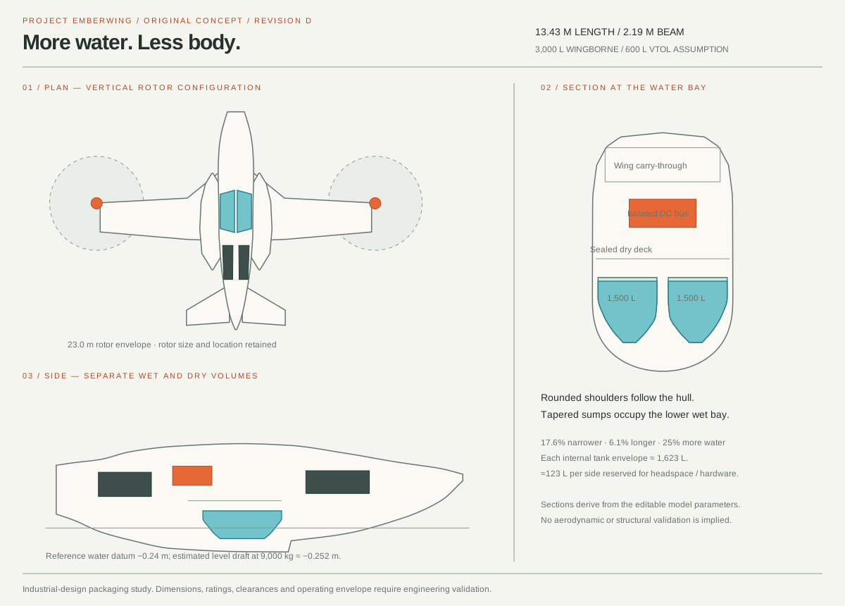
Revision D — conformal tanks, slender hull
The old rectangular tank envelopes underused the lower hull. Revision D uses rounded ends, flared shoulders and tapered sumps, with separate sealed tanks arranged symmetrically around z = 0. These are original Emberwing packaging assumptions; no internal Thunder construction is inferred. Tank shapes can be tailored to available space, but their stiffness, access, baffling and drainage need separate design. NASA's Assemblies of Conformal Tanks provides a general packaging precedent, not validation of this aircraft.
| Dimension / capacity | Revision C | Revision D |
|---|---|---|
| Hull length | 12.658 m | 13.429 m / +6.1% |
| Maximum hull beam | 2.657 m | 2.190 m / −17.6% |
| Water payload assumption | 2,400 L | 3,000 L / +25% |
| Full gross mass assumption | 8,400 kg | 9,000 kg |
| Provisional vertical water load | 600 L | 600 L |
The shell uses a uniform width modifier, replacing the preserved-width wet-bay bulge. The roof and wing-root fairing are lower; the sealed dry deck follows the hull taper at y = 0.66 m. Generator, cooling, fuel and avionics envelopes are repacked. The full 5.8 m rotor diameter and its pivots are retained. Main gear sits 0.30 m farther aft, and the door panels narrow with the hull. Sealed bow cells, structure, ventilation and installation gaps remain intentional; filling every cavity with water would conflict with buoyancy and dry-system access.
Closed-mesh integration gives 1,500 L per tank at full water level. Each interior shell envelope encloses about 1,623 L, leaving roughly 123 L for vent headspace and internal hardware allowances. Water volume is calibrated against triangulated geometry, not a bounding box. The effective rated capacity still needs physical verification after detailed baffles, vents and drainage are designed. At 101 fill fractions, the interpolated GLB-compatible water shape differs from its target by less than 0.72 L per side; symmetry is preserved. The water level follows the nonlinear volume/height relationship instead of scaling a box.
Rigid packaging tests find approximately 55 mm between sampled tank-shell vertices and the hull envelope. The tested primary equipment meshes remain inside the hull, and gear vertices do not enter the tank envelope at 37 retraction positions. This is not a complete swept-volume, plumbing, maintenance-access or structural clearance audit. The cutaway now exposes the starboard lower hull and sump outlets. Reproduce the checks with npm run verify:packaging.
The section union estimates 9.18 m³ displacement at the revised reference datum y = −0.24 m; 9,000 kg corresponds to approximately y = −0.246 m in level fresh water. The old reference datum was −0.30 m. The slimmer hull draws more water; no dry-mass saving is credited. This coarse result omits trim, rake correction, wave and slam loads, flooded compartments, planing and roll stability. It cannot establish amphibious feasibility.
Revision F — integrated surfaces and mechanical finish
The dorsal wing saddle now meets the wing in position and tangent; overlapping root skins are trimmed away. Tail-root shoes, cooling hoods, recessed exhaust throats and fitted aerial mounts resolve the upper-aft junctions. Airfoil and loft normals are calculated from their surfaces, and sealed end caps replace open nacelle, blade, float and generator ends.
Recessed main-gear wells have real hull openings and curved covers. Shaped tires, rims, brakes, hoses and axle connections make the undercarriage inspectable. The nacelles gain exposed trunnion bearings, conformal paint and louvres; the water doors gain inner skins, bonded edges and fitted ribs. Generator flanges, isolators, connectors and battery retention details remain conceptual equipment.
Overall dimensions, water capacity, mass allowances and authored mission behavior are retained. Surface topology, normal continuity, fairing joins and gear apertures are tested separately from the existing packaging and motion checks. These checks establish model quality, not aircraft feasibility.
Revision E — continuous flight and a natural environment
A single 7 minute 15 second, 17.9 km sortie uses an original synthetic valley. The aircraft takes off empty from the operations pad, converts to forward flight, follows a curved approach to the lake, captures 3,000 L while planing, climbs wingborne, turns around the northern valley, drops water over the fire line, returns empty around a descending circuit, converts, lands vertically and shuts down. Geometry remains revision D’s slender 13.429 m hull and calibrated conformal tanks.
| Study | Behavior |
|---|---|
| Complete response / 7:15 | One continuous route, not a scrolling straight-line backdrop. Quintic bends meet straight legs with zero endpoint curvature. Position follows an arc-length schedule; heading follows the tangent. Bank follows speed and curvature, with about 38° maximum bank in the empty return. The loaded turn is gentler. The scheduled maximum roll rate is about 7°/s. |
| Scoop / 38 s | 42 m/s approach; establish a 38 m/s planing run; deploy probes; capture 3,000 L over 15 s; retract; accelerate to 46 m/s by 30 s and depart wingborne. The full sortie uses this same water run. |
| Drop / 22 s | 45 m/s, 35 m assumed reference height above the fire clearing. Paired doors open 0.18 s apart to about 31°. A 4.2 s release empties the tanks. Four initial streams break into a dispersing plume; impacts follow the local terrain and form a wet swath. |
| Reduced-load departure / 38 s | The separate VTOL study retains 600 L. The full sortie departs and returns empty. Neither sequence performs full-load VTOL. |
In the complete sortie the fuselage remains level during vertical hover and landing. Wingborne pitch follows climb/descent; flap, aileron and ruddervator controls articulate with the authored state. The early climb clears the rising ground beyond the pad. Gear extends before landing and the rotors coast down after touchdown. Speeds, heights, RPM, control deflections and the conversion corridor are design assumptions, not manufacturer performance claims or a closed-loop flight model.
The scenery is a 13 km square procedural height field, with a roughly 1 km wide, 3.6 km long lake, irregular shores, distant ridges, forest stands, a fire clearing and a small base. It represents no real location. Local photographic ground textures are CC0 assets from Poly Haven: Rocky Terrain 02 — Amal Kumar and Forest Ground 04 — Rob Tuytel / Rico Cilliers; see the asset license. All other scene textures are reproducible procedural assets. The Three.js water rendering example informs the use of planar reflections and animated normals.
The renderer now shades normals per fragment and preserves material distinctions. Hardware/full mode uses physical materials and environment lighting. Adaptive mode uses less expensive per-fragment lighting on software GPUs, fewer surface samples and reduced moving resolution; hidden internal components are omitted from exterior drawing. Both modes retain the same editable source assembly, curved surfaces, material names and control behavior. Cutaway and explosion restore the internal parts. Forest detail uses instanced crossed foliage cards rather than individually simulated trees; software mode uses a terrain-conforming projected aircraft shadow, terrain/forest level of detail and an approximate Fresnel sky reflection. Full mode uses dynamic shadow maps and planar water reflections.
Water parcels inherit the aircraft’s world velocity and correctly transformed door locations. Gravity, linear drag, lateral spread, fragmentation and soft impact mist form a coherent illustration. The four deforming sheets follow the scheduled door release and flow. Foam, spray, smoke, wind, flames and the wet footprint remain visual approximations; there is no validated fluid, drop-coverage, fire-suppression, gust or wave model. The 3,000 L fill/release schedules are mass-conserving independently of the decorative particle density.
Pause, scrub, replay, click a phase or select 0.5×–8× playback. Cinematic follow, free orbit and route overview use the same geography. Validation samples the complete sortie and focused studies, checks terrain and rotor envelopes, matches displayed speed to geographic motion, checks emission transforms and integrates water flow. Passing these checks establishes consistency of the illustration, not airworthiness. Verification data and reproducible scripts ship with the editable project.
Historical mass and power sanity check · superseded
Full-payload VTOL is excluded. The same tank capacity must not imply the same vertical-lift capability. The model allows inspection poses independently of loading; its status indicator flags water above the provisional VTOL limit.
| Assumed mass item | kg |
|---|---|
| Hull, wing and tail structures | 2,300 |
| Rotors, motors, inverters and tilt mechanisms | 900 |
| Two turbine-generator assemblies | 700 |
| 80 kWh buffer pack (200 Wh/kg, optimistic pack basis) | 400 |
| Water tanks and handling | 350 |
| Landing gear | 350 |
| Avionics, cooling, wiring and remaining systems | 400 |
| Dry estimate, not a weight statement | 5,400 |
| Illustrative fuel load | 600 |
| Light / full water load | 600 / 3,000 |
| Light / full gross mass | 6,600 / 9,000 |
Assume two 5.8 m diameter rotors, total disk area A = 52.84 m²; non-overlapping disks; sea-level density ρ = 1.225 kg/m³. Ideal momentum theory gives Pideal = W^(3/2) / √(2ρA). Estimate bus demand using figure of merit 0.72, motor/inverter efficiency 0.92, a separate 12% allowance for installation effects and control margin, and 35 kW auxiliaries: Pbus = Pideal / 0.72 / 0.92 × 1.12 + 35 kW. The margin is not a validated safety factor. Momentum theory is a lower-bound calculation, not a rotor design. [9]
| Gross mass | Ideal hover | Estimated bus, sea level | At ρ = 0.95 |
|---|---|---|---|
| 6,000 kg, dry + fuel | 1.26 MW | 2.16 MW | 2.44 MW |
| 6,600 kg, light load | 1.45 MW | 2.48 MW | 2.81 MW |
| 9,000 kg, full load | 2.31 MW | 3.93 MW | 4.46 MW |
Proposed installed supply: two 1.15 MW continuous generators plus up to 0.70 MW battery boost = 3.0 MW peak bus power; two 1.4 MW peak shaft motors. These are aspirational sizing assumptions, not selected hardware. With 64 kWh usable from an 80 kWh pack, an ideal 0.70 MW boost lasts about 5.5 minutes before reserves, ageing and cooling constraints. The implied 8.75 C discharge is demanding and unverified. At 6,600 kg, nominal generator power alone is insufficient for the estimated hover; battery state and thermal condition matter. Density reduction sharply erodes margin. No single-generator-out hover is promised.
Nominal lifting planform is about 45 m². At 9,000 kg and 38 m/s, required CL is roughly 2.2: aggressive and dependent on unvalidated high-lift devices and rotor slipstream. At 45 m/s it falls to about 1.6. Accordingly 38 m/s scooping is an exploratory assumption requiring water-supported planing, and 45 m/s is an illustrative exit target rather than a proven takeoff speed. Hull drag, stall margins and takeoff distance remain unsolved.
Historical water and rotor-clearance logic
Rotor pivots are at x = ±8.6 m, y = 3.85 m; the rotor plane is 1.50 m ahead along the nacelle axis. With water datum y = −0.24 m and 2.90 m radius, the flat-water tip gap in forward mode is 1.19 m. During upward tilt θ, the lowest disk point is 3.85 + 1.50 sinθ − 2.90 cosθ. This static gap excludes blade flex, spray, waves, roll, pitch and hull heave. At 5° roll, the outboard geometry alone can consume around 1.0 m of vertical margin. No wave-height operating limit has been established.
Two aft-of-step probes feed the central tanks. An assumed 200 kg/s combined capture rate would add 3,000 L in 15 seconds. At 38 m/s, the minimum forward momentum drag is approximately 7.6 kN and corresponding towing power is 0.289 MW, before probe/hull losses. Water stagnation pressure is roughly 0.72 MPa. Ram capture does not supply free water: drag, water hammer, venting, slam loads and CG transients must be designed and tested. The revised 38-second scoop study preserves the full 15-second capture interval, with brief flux ramps and 200 L/s average flow. It remains an authored operating study, not a validated simulation.
Current operating assumptions
- Light vertical staging: empty water tanks only, subject to unresolved density, fuel, battery and power limits. No hovering over a lake to scoop.
- Wingborne scooping: rotors fully forward, gear retracted, doors shut, probes lowered only on a suitable planing run. Automatic mass limit and independent abort logic required.
- Full-load exit and delivery: remain wingborne after capture, release through four doors, then return light. Full-load land departures use a runway; full-load vertical departure is outside this concept.
- Water taxi / buoyant rest: possible in concept with probes and gear retracted, but stability, draft and propulsion practice require separate analysis.
Unresolved engineering questions
- Conformal-tank manufacture, reinforced sump and door structure, usable-versus-gross capacity after hardware, residual drainage and access. The added 600 kg water load has no validated structural mass allowance.
- Weight growth, generator and battery thermal rejection, fuel endurance, blade aeroelasticity, wing bending and whirl flutter.
- Transition corridor, motor-out controllability, failure isolation, autorotation or emergency landing strategy, and safe conversion with limited wing lift.
- Real hull displacement, porpoising, step ventilation, high-speed spray envelope, fatigue and seawater corrosion.
- Symmetric tank filling/dropping, slosh loads, emergency jettison, water hammer, overflow sizing and door actuation against water pressure.
- Autonomous water/obstacle perception in smoke, glare and waves, airspace coordination, drop accuracy and human authorization of firefighting missions.
The digital clearance tests cover rigid model geometry only. They cannot validate any item above. All internal equipment is a packaging study. There are no weapons or combat systems in the model.
Linked research bibliography
Aircraft sources reviewed 12 October 2026; Thunder exterior references rechecked and interface reference reviewed 13 October 2026. Primary sources; short paraphrases. Public claims may change as Thunder develops.
- Anduril — Thunder. Product identity, tiltrotor and series-hybrid claims. The text extraction encountered a JavaScript gate; the original page HTML exposed manufacturer image assets, whose product render and display photographs were inspected for revision B and rechecked in the live browser for revision G. The Halo-labelled photograph was used only as a shared-platform exterior reference.
- Archer / Anduril joint announcement, 20 July 2026. Dual tiltrotors, RPM variation, architecture and stated development schedule.
- De Havilland Canada — Aerial Firefighters. CL-415 tank capacity and four-door distinction.
- TSB — Aviation Investigation A13A0075, §1.6.1 and auto-probe discussion. High wing; tank/probe/overflow configuration; overloading hazard. The original HTML direct fetch returned 403; indexed section text and the official PDF were identified.
- USFS — CL-415 Amphibious Water Scooping Aircraft User Guide V4, 29 June 2018, pp. 4–5. Planning, fill-time distinction, tank/door configuration. Operational guidance for the CL-415, not Emberwing.
- Bell — Tiltrotor technology. Vertical/forward thrust-axis transition principle.
- NASA — Electrified Aircraft Configurations. Series versus parallel and turboelectric definitions.
- NASA/CR-2018-219897 — Examining the Conceptual Design Process for Future Hybrid-Electric Rotorcraft. Architecture and sizing tradeoffs.
- Wayne Johnson / NASA — Influence of Lift Offset on Rotorcraft Performance, NASA/TP-2009-215404 (2009). Hover figure of merit and projected disk-area convention.
- Dornier Seawings — Seastar design / sponsons. Primary precedent for centre-fuselage sponsons and amphibious gear integration. Emberwing dimensions and hydrodynamics are independent assumptions.
- NASA Tech Brief — Assemblies of Conformal Tanks (2009). General space-efficient tank packaging precedent. The indexed abstract was available; the direct NASA page/PDF returned 403 during this review. No tank dimensions or strength claims were taken from it.
- NVIDIA GPU Gems, chapter 1 — Effective Water Simulation from Physical Models. Combining geometric waves with finer normal-map waves and analytic surface normals. A real-time visual approximation, not a validation of Emberwing hydrodynamics. Reviewed 14 October 2026.
- USDA Forest Service — Airtanker drop guide. Operational context for how release flow, height, aircraft speed and wind affect coverage. Aircraft-specific guide data are not transferred to this concept. Reviewed 14 October 2026.
- Musée de l’ingéniosité J. Armand Bombardier — CL-415 scoops. Original hardware artifact photographs and approximate opening dimensions; front and profile photographs inspected 14 October 2026. Used for visible form only.
- Aliano43 — Bombardier 415 Probe. Original installed-probe photograph, 16 February 2006, CC BY-SA 4.0. Inspected as a visual reference; no image or derivative texture is bundled in the model.
- John K. Hawkshaw / Field Aviation — US4474350A, Probe for water bomber (1984). Primary technical precedent for a curved retractable probe aft of the step and an upward jet entering a separate receiver. Not an identification of CL-415 production internals. Reviewed 14 October 2026.
- FAA — Pilot’s Handbook of Aeronautical Knowledge, chapter 6: Flight Controls. Primary reference for aileron direction, differential travel, flap function, and symmetric/differential V-tail mixing. Concept gains and travel limits are original assumptions. Reviewed 14 October 2026.
- DOI / USFS — Interagency Aviation Lessons Learned 21-02, Firefighting Flight Operations (29 January 2021). Primary operational context for flights of scooping aircraft, coordination and spacing. No numerical separation limit was transferred to Emberwing. Reviewed 14 October 2026.
- FAA — Seaplane, Skiplane, and Float/Ski Equipped Helicopter Operations Handbook, chapters 2 and 4. Stepped hull and planing principles; no hull sizing or performance data transferred to Emberwing.

Model authorship: original procedural geometry for Project Emberwing. No manufacturer CAD, textures or logos are incorporated. The EMBERWING mark is original lettering.